



REPAIR POWERMAC G5 PSU
THE APPLE POWERMAC G5 WAS A GREAT EQUIPMENT AT THE TIME, APPLE DECIDED TO STOP PROVIDING TECHNICAL SERVICE TO THIS COMPUTER SINCE 2010, FOR ANYONE WHO WANTS TO REPAIR THEIR POWER SUPPLY, HERE YOU CAN FIND A CHEAP AND EFFECTIVE SOLUTION
This video summarizes the steps to follow to repair a damaged PM G5 power supply, replacing it with a cheap PC power supply (600 w)
This procedure is based on what has been seen on this page, the idea basically consists of reviving your old Apple Power Mac G5 (very useful for many tasks such as desktop publishing, graphics and Photoshop) using the power supply of an ATX type PC computer. about 600 watts of power.
All the information that is given on this page is for illustrative purposes without guarantee of any kind, if you do it it is for your own interest and you must always take all the security measures that are required in your country so as not to suffer any type of accident. .I got a positive result but I can't guarantee anyone that I can do the same
1. Background
My Mac G5 has worked for me for several years, however its power supply is very problematic, suffering two breakdowns with a very high repair cost.
In the last failure, my surprise was important when Apple Technical Service refused to repair this computer, claiming that it was old and that it was out of technical service coverage.
A zero for Apple for its lack of support for its customers, not providing a solution of any kind is not reasonable for a computer that cost more than 2,500 euros at the time
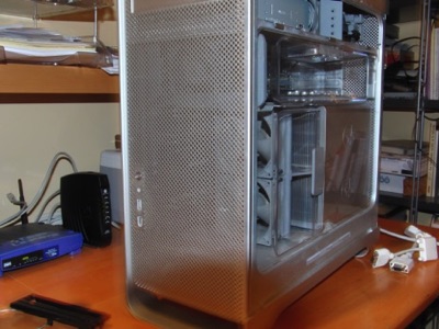
It's easy, to know if the source of your Apple PowerMac G5 has been damaged, it just won't start, they are problematic power supplies, as soon as an additional hard drive is added to the computer they usually cause problems, even at the time Apple campaigned to withdraw a whole series of them due to their malfunction, unfortunately, my team was not on the list.
2) Access the power supply
n any case, whether you decide to repair the power supply or if you decide to replace it, you will have to access it, which you can do by following these simple steps.
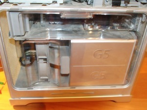
Find a large and clear place in your house, place the computer without any type of element connected and wait a while if it was plugged in so that all the current that the capacitors of the FA (power supply) could store is discharged.
The first thing is to remove the aluminum side door and you will access another plastic door that is very easy to remove, pulling out by its handle.
At this time it is better to lay the computer on its side to be able to continue working
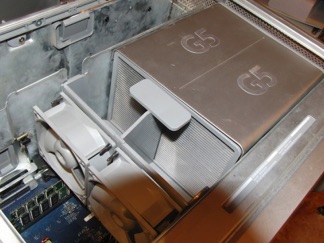
Start by removing the fans from the processors, they are pulled from above, they are connected by pressure to a black connector that is on the motherboard.
It may be a good time to thoroughly clean all the elements that you are disassembling, since they will surely be very dirty and full of dust, which is usually the cause of the problems of these PSs.

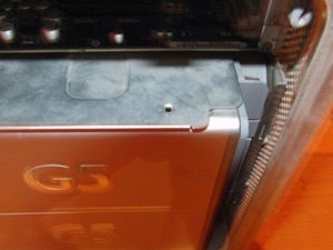
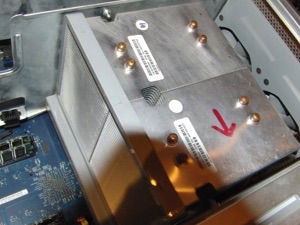
The time has come to remove the covers from the radiators of the processors, in the photo you can see a small hole, in some cases you have to remove a small plastic cap that prevents them from moving, in my case it was not there, I imagine that in the last repair someone forgot to put it on or simply did not consider it important, they are removed by moving them slightly to the front and then upwards
Well if everything has gone well we will see the radiators of the processors that are those aluminum boxes, the first thing is to mark with a marker the processor that is in the lower part closest to the FA, and then when reassembling them, place them in the same site, this will avoid certain problems with the fans and having to pass software to the computer to reset it. In the image you can see the guides where the covers that we have removed before go.
Remove a plastic trim located in front of the radiators marked in green

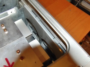
The next step is to remove the rear fans, they have two small plastic hooks that you have to sink, move inwards and pull up, but first we must release the connector to the board that is located in the PCI card area of the computer.
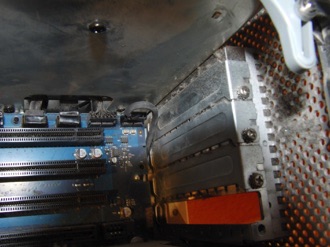
We will remove the graphics card from the computer and we will be able to access the location of the connector of these fans in the following image
This connector must be removed after removing the graphics card, taking care not to damage it when removing it, because it goes under the metal plate that separates the processors from the graphics card compartment
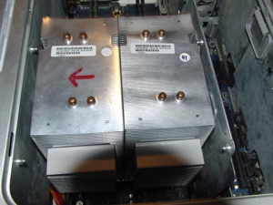
If you have followed the steps up to here, the processors should appear as seen in this image, where you can see even better the hooks that are used as guides for the bezels or covers of the processors.
Do not forget to also remove the memory from the motherboard and mark with a marker the order of placement that it had on the motherboard to avoid problems
The time has come for the most complicated operation, removing the processors that are attached to the radiators forming a single unit.
Each one has four special screws, Apple uses a special type of screw, I used a modified allen key type tool to fit them, the tool that is officially used with these screws is called T15, I was not able to find it anywhere industry store.
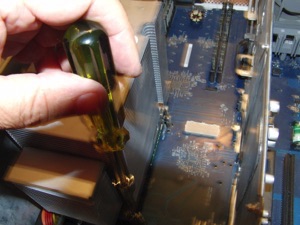
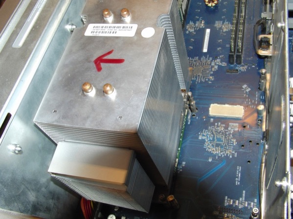
They are extrusion screws (marked in the photo in red), they have a very curious operation. To secure the processors in place and at the same time allow their installation, these screws when loosened but inserted into the plate allow the processor to be moved and removed from the connector that goes on the motherboard, by tightening them what we do is change your radio making it bigger and thereby locking the processor in place.
It is about facilitating its installation by leaving the screws already inserted (although loosened) in the plate to be able to place the processor in its place and then simply tighten it so that it stays in position. When we put the processors back, remember to leave them inserted but loose in their position. place, after putting the processors we tighten them.
In the image in green you can see the processor connector that has already been removed
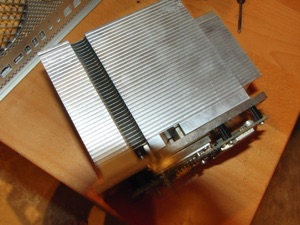
In the image a processor with its cooling plate removed from the motherboard
We have to remove not only the fastening screws of the processors but also their hook to the computer case to be able to remove the FA later.
We will use a small adjustable wrench or a fixed wrench, taking special care not to damage the motherboard
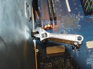
To remove the metal plate that separates the processor compartment from the FA, you have to loosen a couple of star screws that attach it to the FA and then turn it inside the plate as shown in these photos, in order to be able to extract it later.
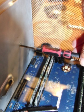

At the bottom of the computer you also have to loosen four screws to be able to free the power supply
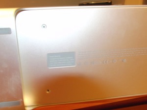
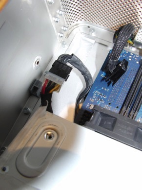
To be able to remove the FA we will first have to free all its connectors.
Two go to the plate and one is aerial, that is, it is connected to a cable like the one shown in the red circle photo
The image also shows the loose connector that connects the board to the USB panel and the power button on the front of the computer, which we can disconnect to work more comfortably, in the green circle
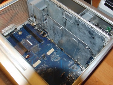
This is what the computer should look like after removing all the previous components.
It is important to group and classify all the removed screws to later know where they went.
2) Repair or replace the power supply
This is the first dilemma we will have to face.
This is the FA of our computer, there are several possibilities, the first is to buy a used one, the truth is that these sources cause problems and it will break again, another solution is to see if there is any burnt component visible and replace it with a new one, this not usually, the components can also be relatively expensive (7 euros a CI) so you can spend a few euros for nothing, let's continue the disassembly process to take a look.
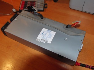
We will loosen the screws and take off a transparent plastic protection to access the PS plate.
It is striking, the impressive printed circuit board (which I will use to make a Quadcopter) full of bovine radiator transistors and a multitude of capacitors, it is understandable that Apple had a high price for this source, which on the other hand has given such a bad result
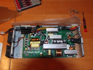
In my case I saw a burnt IC and proceeded to replace it with a new one (7 euros) but it did not work, the FA continued without starting. Even if you don't see it, there are always more damaged components that must be replaced for the board to work.
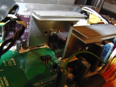
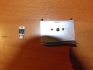
I only had the following option left, to replace the FA with a PC one, they are very cheap (20 euros) and if they break you can put another one for very little money, the procedure is surprisingly simple, because the colors of the cables (thanks to the standardization) are the same so it's hard to go wrong, this is the step by step process
3) Replace the PM G5 power supply with an ATX type PC power supply
The first thing is to choose the appropriate source, it must have at least 600 w of power to be able to power the G5 correctly, the second must be of the ATX type, this guarantees that it will be able to turn on when the button is pressed and that it has all the necessary voltages except one that, as we will see, is not essential for our computer to work.
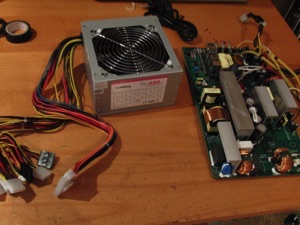
Here we have our pc font, it looks very tall but it will fit perfectly in the box of the old Mac G5 FA.
It is low-end so its price ranges between 20 to 25 euros in any computer store can be purchased.
Before continuing, it is convenient to check that it works, for this we connect it to the current and make a jumper on pin 14 (green + 2.5 v) of its ATX connector with ground, this should make the fan working, if not , it is probably faulty.
We proceed to disassemble the box and see how small the plate of this FA is in relation to that of the G5, and we will have doubts as to how it is possible that this source can do the same as the other being three times smaller, because if does, as we can check later
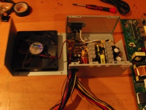
We desolder the 220 v power cables that are black and white and that go to the female plug of the PC FA, we also release the fan connector from its place and free the screws to be able to release the plate from its metal box where came, it should be as seen in the photo
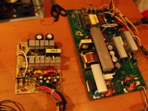
The first thing that we will solder is the G5 FA plug connector that we will previously cut, we will use whenever possible a heat shrink protector to protect our soldering and make our transformation safer and more professional
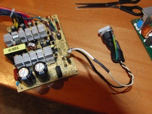
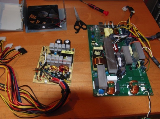
The difference in size between the two plates really does not cease to amaze, is it a matter of technology that has advanced so much in this time or is it simply a question of reducing costs.
The truth is that as you can see later it works perfectly, with less noise and producing much less heat than the original source.
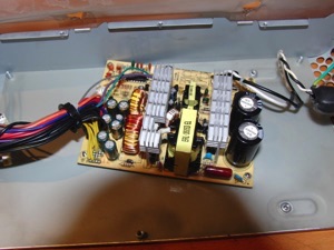
To mount the plate of the new source in the box of the FA of the G5 we will look for a support on the plate that is the most appropriate in my case use this, placing it as centrally as possible so that it fits well and can be ventilated without problems
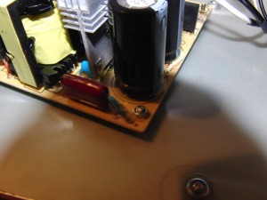
To fix it I made a hole in the box and passed a screw with a spacer to screw the plate, for the rest it is enough to put spacers or fix with more screws if desired
Then connect the most appropriate fan to the fan cable of the new board, just one of them, leaving the other disconnected
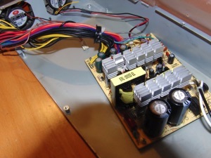
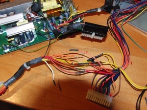
The procedure below is laborious but simple, it is about connecting one by one the cables of the new board to the connectors of the FA of the G5, we will cut them in the FA of the G5 as close as possible to the board
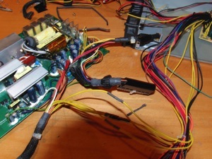
In the PC's FA there are more cables than necessary, so we only have to worry about distributing the cables well, taking care above all that those that carry more amperage are well distributed.
Here you can see the detailed wiring of the ATX connector of the pc
Below you can see the connection diagram of all the connectors (3) of the FA of the Power Mac G5
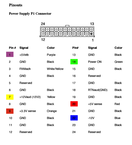
The only voltage signal that we will lose when making this change is marked as number 8 of the +25v P2 connector, this is used for two things that I know of, turning on the G5 boot led and powering some special Apple monitors that they use that current through the connector of the card, quite infrequent and that is not my case, regarding the light of the led it does not seem important to me either, so its light can be dispensed with
The P3 connector carries power to the hard drives and the DVD, so we must pair it with them in the case of the PC FA, as explained before.
We see later photos of the process of cutting, welding and isolating each of the cables.
We must distribute the cables between the 12v1, 12v2 and 12v3, which are the most amps moving from the source, ensuring that the wiring is conveniently distributed.
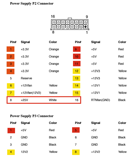
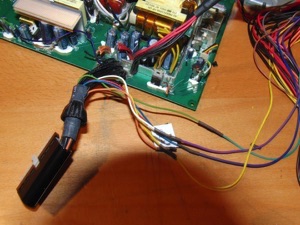
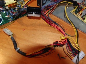
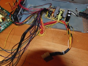
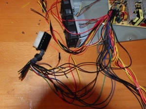
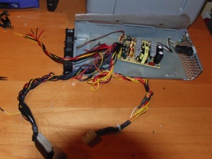
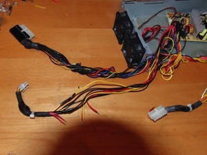
This connector that I left for the end is the one that carries power to the hard drives and the DVD, so we will have to use those that fulfill the same function in the PS of the PC
Once the wiring is finished, we pass them through the same holes they had before
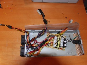
We close the box and this is how it should look, our cables are somewhat longer and this will allow us to later assemble everything more easily
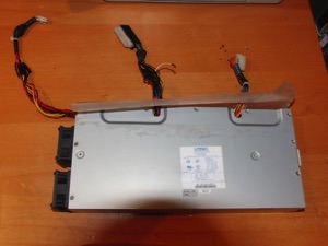
We see how we place the cables, in this case carefully because in this place the processor will go later, we will have to leave space for its installation
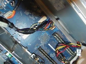

We will place the screws of the inferior part
We reconnect everything after putting the metal separator and screwing it to the modified PS
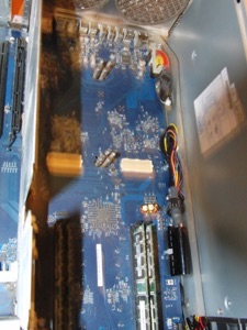
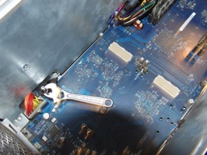
We put the screws of the processors back and follow the reverse process of the disassembly described above
4) Power ON
The moment of truth arrives, do not forget to install the memory that we removed since otherwise it will not start, if it does not start, check also if the source is running by the sound of its fan, if it works and the computer does not start, the problem may be from the motherboard.
But hopefully that is not the case and your Apple Mac G5 computer has come back to life.
Good luck in the attempt and I hope that this small manual has been of help to you.