



IT'S TIME TO DESIGN OUR OWN QUADCOPTER LOW COST, THE EVOLUTION OF TECHNOLOGY ALLOWS AN ATTEMPT THIS PROJECT FOR LESS THAN 130 EURO
ICARUS III QUADCOPTER
4 ENGINE AND A CONTROLLER BOARD
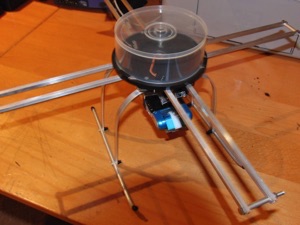
This is the basic foundation of a quadcopter, of course there are three, six, eight, and more and some are even able to lift people and have recently made in Germany, so there is a whole world of possibilities for these devices.
The basic idea consists of a control board with a processor with one or more software and devices or sensors that analyze your orientation in space on three axes and impulses that send orders or some regulators which in turn accelerate or slow down the four engines coordinated to achieve stability in space. In addition to this the aforementioned controller must also interpret the orders received through RC receiver of the person who handles remote and move the device according to your instructions without losing stability above all no doubt a technological challenge
EVOLUTION
Like all technological advances in its infancy, this was really an invention very expensive, more development in Germany where some companies had at first designed business models prohibitively expensive, but showing the possibilities of the idea.
Little by little, thanks mainly to the selfless efforts of many who gave up their software development community through open projects, and cheaper hardware (sensors and processors, motors and controllers) arrived today (end of 2011 ) to look very closely at the construction of a Quadcopter at an affordable price (under 130 euros) which is stable and capable of moving a camera (video or photo) of about 150 grams.
ICARUS III PROJECT LOW PRICE QUADCOPTER
This is the objective of Icarus III, have a little money quadcopter be something more than just a toy and let us take pictures and videos from the height (in addition to having fun with their use).
The load capacity should be enough to ship a camera about 150 grams and if possible some streaming video device to see from land that is focusing the camera and thus ensure the best frame, although this last not really necessary since it is difficult to handle the quadcopter and simultaneously look the viewfinder to frame the picture
CARACTERISTICAS ESENCIALES DEL PROYECTO
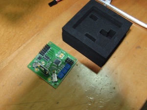
As for the control unit we cannot choose other than the HK KK version, HobbyKing Quadcopter Control Board V2 (Atmega168PA) (http://hobbyking.com/hobbyking/store/uh_viewItem.asp?idProduct=19534), if we want To keep us below the marked price, this unit generally has a bad press but there are numerous videos on YouTube that prove that it can be installed, configured and that it works reasonably, so in principle if others have done it I can too (I imagine).
1) Weight in the range of 50 to 60 grams ( x 4, 200 to 240 grams total)
2) Between 800 kv and 1100 kv (slow motors)
3) Thrust between 600 to 800 gr (x 4 2,400 to 3,600 gr total!!!)
4) Consumption in amps between 8 to 14 amps
5) Propellers between 8 to 10 inches (against the slower the motor (less kv) and the bigger the propeller I suppose)
6) Esc or regulators between 25 and 35 amps minimum (be careful here, the manufacturer's figures are usually not real, it is better to spend something than burn the esc, also here the weight is important, it must be between 50 and 70 grams.
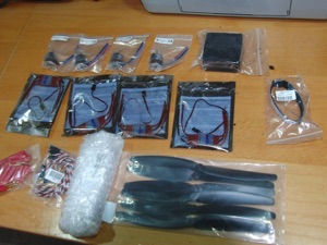
Indicare la lista de los componentes que he pedido a HK y que incluidos los portes su importe es inferior a los 120 euros (pendiente de aduana), pero esto no es significativo, (ademas no se si funcionara) generalmente los componentes suelen cambiar y solo se debe pedir sobre material en stock por lo que es mejor ser flexible para poder saber elegir otros componentes.
Code
AX-2210
NTR_B25A
QUAD-CON16K
HCB-10
AM-2005-M-15
T2200.3S.30
AM1009x10
Turnigy-HKLP
Qty
4
4
1
1
19
1
1
1
Description
2210N 1000Kv Brushless Motor
TURNIGY Basic 25A v3.1 Speed Controller
HobbyKing Quadcopter Control Board V2 Atmega168PA
10X6 Propellers (Standard and Counter Rotating) (6pc)
15cm Male 22AWG Twisted (10pcs/bag)
Turnigy 2200mAh 3S 30C Lipo Pack
HXT 4mm Gold Connector w/ Protector (10pcs/set)
Turnigy Battery Strap 330mm
INVOICE TOTAL: SHIPPING:
Each
$7.55
$15.86
$24.79
$3.48
$2.29
$13.79
$3.64
$1.59
Total
$30.20
$63.44
$24.79
$3.48
$2.29
$13.79
$3.64
$1.59
$143.22
$19.5S

From the list you will see that lack the chassis, but HK has a chassis cheap wood and fiber, widely criticized for his weakness, I think in this section if we try to do something interesting and more personal.
No matter how cheap it is, if it breaks we'll be asking us to pieces and making them is sometimes difficult to copy a piece made industrially. I have taken the trouble to design and make an aluminum and fiberglass, with elements cheap as aluminum rods square, round and flat, (Leroy Merlin) used printed circuit boards, a box of DVDs and some screws with nuts lockable, elements accessible to anyone, without requiring much skill to complete.
The advantage is that you can adapt elements as carriers of cameras etc more easily, and if it breaks make the piece is very simple, just repeat you did, the price of the materials of the assembly (no screws or nuts) is below 9 euros, weight camera support, a servo to tilt the camera and the receiver is 380 grams. see the construction process step by step
Also missing from the list adapters for carrying propellers or propellers, which serve to place the propeller on the motor, and HK did not have in the shop, so I buy to at 2.50 euros in Tormodel for each motor shaft is 3 mm and propeller shaft 5 mm, so I had to open the orifice of the propeller to 5 mmm propeller shaft.
Everything begins here
1) Build the frame
Materials: Aluminum & Fiberglass
Estimated cost: 9 euros
Aluminum flat bar 10 X2 1.70 euros
10x2 aluminum round tube 1m 1.65 euros gross
6X6X1 raw aluminum square tube 1m (x2) 2.90 euros
Before we do anything, we have some basic tools to work properly, it is also important to have a clear space as possible. Using cutting tools involves taking certain security measures to protect us all and hands over the eyes of any material that could harm them.
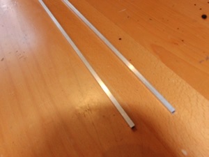
A good gag is very important to fix the pieces to be cut or filed, also a metal saw with leaves, a slow speed electric drill with bits of new 2, 2.5 and 3 mm, a jigsaw to fiber cutting boards and files to smooth the cut material.
Screwdrivers, nippers, scissors, small wrench and a soldering iron and tin solder heat shrink tubing to protect the welds.
Video summary of the construction of the structure of the Icarus III quadcopter low cost
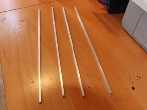
Start cutting the raw aluminum square tubing 6X6X1 1m (x2) into pieces of 50 cm.
Cut also separator tube 23 mm round.
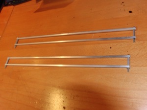
At the ends of the tubes 3 mm holes will spend a few screws and spacers uniondolos in pairs as you can see in the picture.
These spacers are removed to mount the brackets when the motors fit at the end.
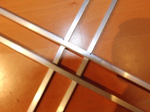
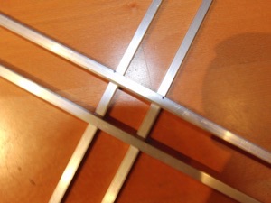
To cross these naughty and start creating the structure of our quadcopter need to make some cuts the bars so they can be mounted on each other.
To which place them above some of the others focused very carefully so that all is as balanced as possible.
Marked with the pen the lines cut.
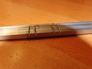
We cut only the first half of the tube
Remove the remaining material with a fine saw hacksaw
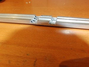
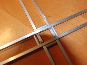
We will use a 23 mm spacers to ensure that the tubes or profiles are at the correct distance
We need to make two sheets of fiberglass 10 X 10 cm, we can use any printed circuit board or card any old computer that we use, the fiberglass is very strong and light, perfect for making our quadcopter have a solid structure and also light.
We must remove all the components that were in the plaque and thoroughly sanded
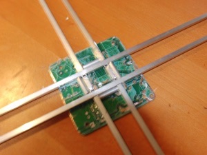
Bottom plate drilled with a hole of 23 mm where the cables pass the top and 4 smaller holes to eliminate weight.
Drilled with 2.5 mm drill bit where they go aluminum sleepers claim the set.
We will use self-locking nuts to prevent loosening by vibration of the engines
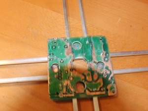
We will use a plastic DVD case to support and protect electronics from shock, is very important to fix it with very elastic material between the frame and plastic using any material that guarantees that do not pass the vibrations to the electronic box, as interferes with the operation of the gyro sensors.
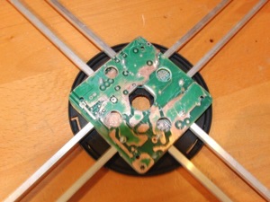
For the landing gear will use bent rod and finished aluminum tube will double in front to prevent snagging on the ground.
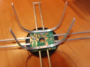
Another landing gear system very simple to do is to put legs under each engine, makes it very stable and is very simple, you can simply use lightweight aluminum or soft to absorb shock.
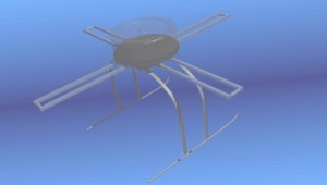
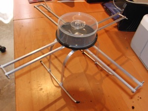
This should be the end result of our structure, ready to house the electronics, the advantage is that in the event of damage we can repair anything because we have previously constructed a very low cost.
2) Mount electronics
Materials:
4 2210N 1000Kv Brushless Motor
4 TURNIGY Basic 25A v3.1 Speed Controller
1 HobbyKing Quadcopter Control Board V2 (Atmega168PA)
1 10X6 Propellers (Standard and Counter Rotating) (6pc)
1 15cm Male 22AWG Twisted (10pcs/bag)
1 Turnigy 2200mAh 3S 30C Lipo Pack
1 HXT 4mm Gold Connector w/ Protector (10pcs/set)
1 Turnigy Battery Strap 330mm
Video summary of the installation of electronics in the Icarus III quadcopter low cost
After checking that all the material we add 4 supports the propeller shaft 3 mm motor buy from Tormodel a company with much material for a good price RC, emphasize the good packaging materials for Hobby King and especially HK KK controller that comes very well protected.
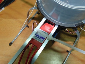
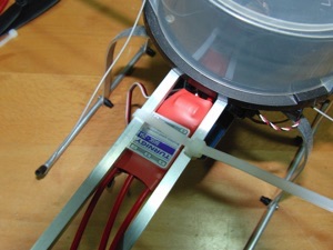
Start mounting esc that will go into the arms of the quad with simple flanges not too hard to avoid damaging them
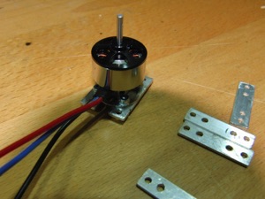
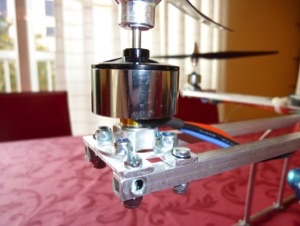
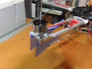
Then we will mount the engines with aluminum rod holes as measured by the engines, it is important here insert rubber washers fasteners to avoid as far as possible vibrations are passed to the quad structure
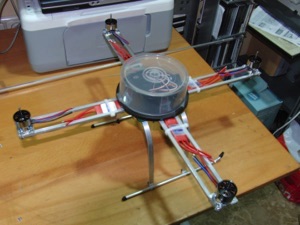
Then we will set the engines on the rods of the structure from borings and locking nut screws, the result should look like this
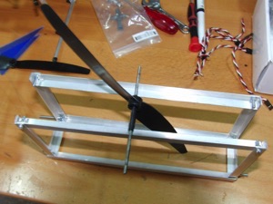
Could this be a good time to balance the propellers, it is very important to avoid vibrations in our quad, HK propellers are poorly balanced and if they are 10 inches vibrations are very large, using this small box of aluminum the props can be balanced by sanding the dark side of the heavier side until it is balanced.
The 8 inch blades on Gaui quad have the advantage of being very lightweight and come pretty balanced so I would recommend its use (10 euros the 4 props).
We then mark one of the arms of the quad in my case I decided to let the back using a few pieces of blue plastic, then you can put leds or something to help us once the quad is flying to easily find the quad orientation in space, this is very important because unless we know we can not direct its orientation and the result will be a certain disaster.
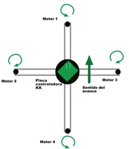
Each arm of our apparatus responds to a specific number and every motor should rotate in the directions shown in this figure, at all times comply with this scheme and we will put the controller board in the direction arrows that mark its progress as we will see .
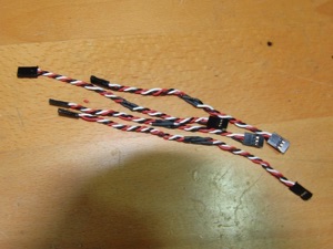
We connect the wires to the KK control board of HK our radio receiver, although these facts cables are sold the price is very high, it is much cheaper to make them ourselves asking these cables from servo to HK and doing so we welded the same colors, it is very simple.
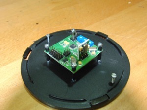
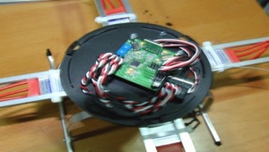
Proceed to mount the controller board HK KK in place and with the proper orientation (in the direction of travel and as centered as possible).
It is very important to fix preventing vibrations affecting them, so we use elastic material, rubber, the protection that cames with the KK control board of HK itself is very useful for this purpose, if the installed rigid structure, does not work and can not stabilize the quad, most of the problems of the quad that do not work well because of this problem is the improper installation of the controller board.
The next step is to solder the wires feeding the esc or regulators, the idea together to connect the cable that connects to the battery.
There are boards very inexpensive to do this but HK does not have available, you must use cable at least 3 mm 12 AWG section to handle the 30 amp electrical installation can be consumed at times.
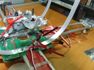
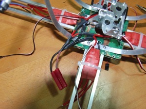
Finally we will use the purchase to make connectors that connect the battery over, these terminals after force soldiers to do until we see which are fixed in place.
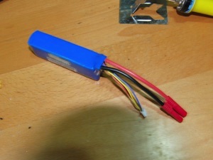
Also changed the connection to the battery monitor especially the polarity is correct.
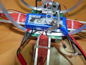
Seek a suitable place for the battery in the Quad, will be the most focused and accessible as possible, with the band we buy can be set where we want, in the photo has been placed using an aluminum cap.
At all times we find that the quad center of gravity is always focused, this will avoid future problems.
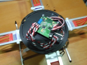
We will set the receiver using a simple rubber due to its low weight and proceed to connect the wires from the esc or regulators to the controller board following the scheme with the corresponding order number.
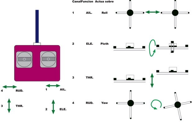
From the handset connected to the KK control board of HK the various channels of our radio, according to the scheme have done, on my radio are well but yours may vary, also observe the polarity.
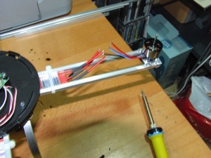
It was time to solder the esc o regulators to the engines, once we pull up the controller to look at the direction of rotation of the engines, to do so by the upper diagram to make it have to change any two of the three wires going to each motor.
We will also adjust the propeller rotation according to the scheme (KK control board of HK original configuration), and we have the quadcopter ready for our first tests.
The great advantage of this controller is the ability to reprogram using a cheap USB device (5 euros) through a software program you can change the KK control board of HK to a different system (number of engines, flight configuration etc) there are numerous free programs to experience compatible with this version of King Hobby KK control board (16k).
If you have reprogrammed the controller using a different firmware (KK) must follow the instructions and the rotation of the propellers of the new software installed
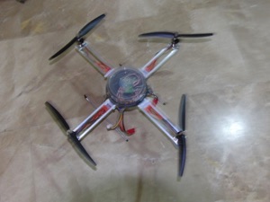
3) Calibration and first flights
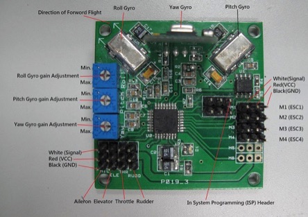
According to this picture of the KK control board of HK can see the location of the gain adjustment potentiometers of the three gyros on our KK control board of HK (Gyro Gain Adjustment).
The first mission is to arm the board. For safety these KK control board of HK do not work if not executed an instruction from the active RC to make them operational before beginning a flight.
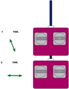
The armed and unarmed KK control board of HK varies depending on the programming that you have been put to the board and usually has to do with the movement of the throttle stick (throttle).
In our case after turning on the radio and connect the board first command will move down to our right and then left down also.
When armed a red LED lights on the board indicating that this ready to receive orders.
Needless to say that all these operations we must do without the propellers on the engines to prevent damage.
(when everything is set up logically they will)
If the board does not arm after doing this, we lower the throttle trim to the maximum, if it does not work will try to reverse the direction of throttle channel, this step is essential to move forward so you do not get discouraged, just try all options to achieve this it is important to have information that could have software that will give us KK control board of HK track like this, if your radio supports channel mixing disable it.
To disarm the board in our case is to keep the throttle stick down to the right more than three seconds if you do this in flight lose control of the quad so it should not do it if not on earth.
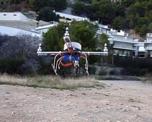
The next step is to see that our controls are functioning properly.
The first is to accelerate gently until the engine is running (after adjust its range).
We put the quad in front of us behind the tail, that is looking forward
Move the right stick (elevator) forward, the rear engine and front should accelerate stand, but this channel is reversed so until it does.
Then move the right stick (aileron) to the left, the right engine should accelerate and left to stand, but this channel is reversed so until it does.
Move the left stick after turning (rudder) to the left, front and rear engine should be accelerated and the left and right stand, but this channel is reversed so until it does.
The next step is to calibrate the esc or regulators.
Is to ensure that the course of the same suit our command of RC.
1) Move the board potentiometer to zero yaw
2) Turn on the transmitter
3) Turn the throttle stop astick
4) Turn on the controller
5) Wait until you hear two beeps after the normal boot beeps
6) Lower the throttle stick to zero, you will hear another beep
7) Turn off the controller
8) Leave the yaw potentiometer position it was before
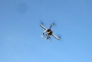
Recommended values for RC radio (if your radio would modify these values, for example mine does not) are:
Elevator to 50% of its nominal value, ie only manage a halfway real stick.
Roll (Aileron) also 50% of its value.
Yaw (Rotation) leave at 100%.
How to adjust the values of the potentiometers.
This task requires a lot of calm and clear thinking.
According to the manual is to start at 50% of its value and begin to increase until it starts to oscilate the quad.
To begin increasing or decreasing the value of the pot depends on the programming of the board, in my case increases in the opposite direction clockwise, you have to do it one by one and not all at once and in my case I have to 78% almost equally in all three, but that value begins to oscillate as shown in the manual, less than 40% almost no effect on the quad.
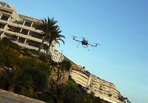
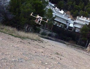
How to reverse the gyroscope (any of them) according to the programming of the original HK
Turn the potentiometer to zero roll
Turn on the controller
The LED will light very fast 10 times
Move the control stick or we reverse the gyro (only one)
The board LED blink non-stop
Turn off the controller
Leave the pot roll in his old position
Prechecking before flight
With the quad in his hand and carefully placed to give motor propellers until you have some strength and we will take it firmly from below.
Force the movement in three axes, if the gyros are all well, the quad will react against our movement trying to stabilize the device in all three axes.
If they are badly acted contrary to destabilize the device, and they are not sensitive enough not to react to our movements.
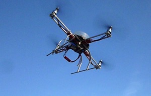
Recall the importance of correct assembly of the controller board must be properly centered and level with the correct direction of travel and above all avoid vibrations that do not work well the sensors.
It is necessary to devote time to ensure that the KK control board of HK is working in the best possible conditions.
Curiously, the most amateurish quad often occur in this sense the best results by leaving more loose boards tend to avoid vibrations that those more solid mounts instead make it impossible to work well at the plate because they convey a lot of vibration.
One way to achieve better results is to look at the outset that the quad is properly balanced, distributing the weight evenly, if we mount a camera on board from the beginning we foresee where so will ensure a balanced package.
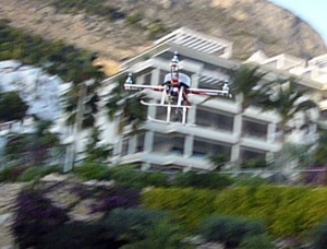
It is also important to balance the propellers, which are the source of many vibrations.
The quad 8 inch Gaui have given me very good result, they are lighter and stronger and make the quad much more agile than those of 10 inches.
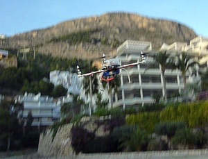
First flights at home and abroad
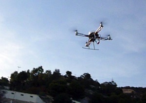
After the first flight home and abroad, we see the behavior of the quad and look for ways to stabilize its flight to make it more manageable, for which the channels looking trimmings total neutrality in flight.
You must get off the ground and kept as static as possible, if from the beginning of the flight we have to maintain its stability will be difficult to control the evolution of flight.
Post the quad on a floor that is as flat and stable as possible, give some energy for gas to rise somewhat above the ground if we see that cut off gas becomes unstable to prevent damage to the blades and proceed to trim until neutral see rising above the ground, is more a work of trial and error, until we get a satisfactory result, if you can fly with more people with quads, so you can share your experiences and receive advice from others who spent at same as you, do not get discouraged and think that if others have done so should get it.
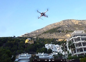
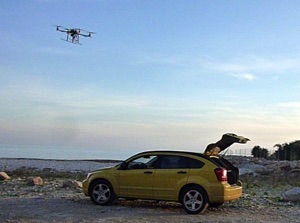
Second flight on the outside near the sea with on board camera Sony Bloggie
New fiberglass frame.
With these rods 6 mm in Decathlon (2.95 euros 120 cm) I replaced the fragile aluminum bars with fiberglass that are lightweight and durable.
Landing gear has also been replaced by a fiberglass 3 mm to be flexible to allow smoother landings.
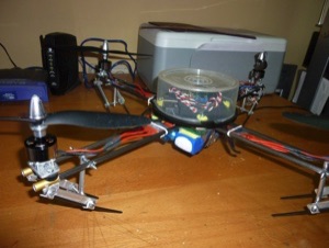
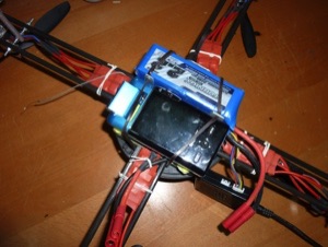
The advantage of aluminum is not deform with the punches, but the biggest problem is that it is very difficult machining, avoid perforated possible to avoid damage.
It has also changed the distribution of the battery and the Sony bloggie to reduce distance to the center of gravity and avoid the pendulum effect it had before.
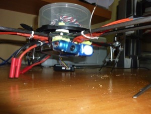
In this video you can see a more stable flight.
Adapting a Canon IXUS HS 115 to the quadcopter
We chose this camera from Canon for our project to make HD video from our unit for several reasons:
1) Low weight of 140 grams
2) High image quality full HD video
3) Low price (118 euros)
4) Compact and robust
5) Out video output that allows FPV
6) Very good camera for everyday use
Video showing how easy it is to reprogram the board using the HK HK ISP programmer and the program (Mac and PC) 0.51 KKmulticopter Flash Tool can be downloaded here (http://lazyzero.de/kkflashtool) and is responsible check us out online for the best version we want to put on our control board HK, in our case 4.7 of Kapteinkuk.
Attention because reprogram the board with the new firmware changes the direction of the yaw gyro, at least in my case
The modifications to the original project can be summarized as follows:
1) 8 inch propellers Gaui quad
They are lightweight, very durable and are balanced are perfect for the size and performance of our engines (8 euros of 4)
2) Fiberglass frame tube (6 mm glass fiber 2.95 euros Decathlon 120 cm)
Lets build a robust and lightweight chassis that is flexible and does not deform in hits, also allows us a very hard landing and resistant
3)Updating the firmware of the HK board to version 4.7 of Kapteinkuk
Guarantees maximum stability in flight and greatly facilitates handling
4) Election of the IXUS 115 camera to make videos in full HD and the possibility of FPV
Video dusty, with the new 4.7 firmware allows the stability to fight the wind without problems.
In this video lifts a load of 500 grams (can carry up to 700 grams).
Displays the new landing gear very resistant fiberglass.
First attempt to adapt the Canon Ixus 115 to our quad.
Bad image due to vibration.
We work on the issue in two ways:
1) Damper mounting of the camera isolation from the vibration
2) Further isolate engines to the chassis to prevent transmitted vibrations blur the image
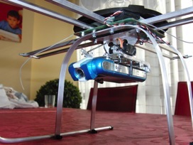
With this small aluminum cage with foam inside is achieved virtually eliminate vibration and it protects the camera from a potential impact, is fastened with three rubbers and easy to install.
In the second part of the video was lost foam element so that vibrations are more than desired, but the system can tell you it works.
These changes significantly improved video quality, plus the camera system works with any standard size market as seen with a Panasonic DMC-ZX1 can be seen in video images.
We use our aluminum cage to mount the Sony DSC-TX10, a camera light (137 grams) robust, waterproof and shockproof, first flight vibration and water in the video that I hope to solve, the video quality of this camera is very high.
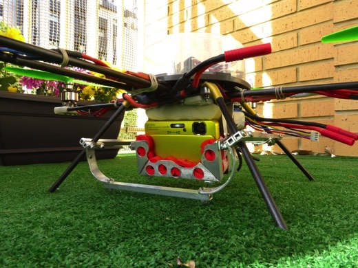
Detail mounting the Sony DSC-TX10.
We use the same cage, somewhat more separate quad body, because the lens is located on top of the front.
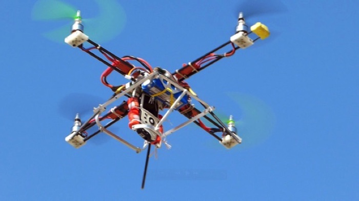
Our low cost Quadcoptero Icarus III latest version with fiber glass and engine mounts in HDPE (High Density Polyethylene)
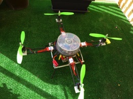
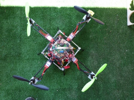
We eliminate the dvd box and cut the top plate to mount the controller directly with a significant reduction in weight and also improve the safety of the plate with an aluminum roll bar, it is also easier access to the replacement of the fiber bars glass support of the motors.
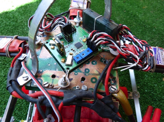
In detail the attachment of the HK board with rubber, prevents vibrations and quad flies smoothly. The cut at the base allows the oscillation of the controller without touching any items.
The roll bar however little aesthetic protects the plate and the receiver in the case of a flip back
New control board Hobbyking KK2.0 Multi-rotor (26-6-2012)
Important new release by HK of this new controller board designed for HobbyKing KK2 by Rolf Bakke by $ 29.9.
With major improvements such as the inclusion of accelerometers, a display to program it without connecting to a computer and multiple pre-programmed settings and automodificables
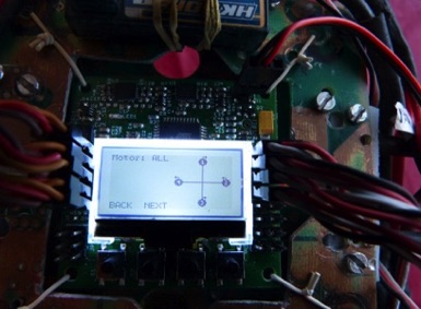
Hobbyking's KK2 control Board
First tests with the new controller HobbyKing KK2 Flight Controller, in this video we can see how adjustments are made prior to beginning to use it in our quad.
The only change that had to do was reverse the yaw channel
Roll/Pitch eje:
Pgain=150
Plimit=100
Igain=50
Ilimit=20
As you can see in the video, the flight is not very stable, the next step will adjust the PI, given that the Roll and Pitch are simultaneously unless you choose to go separately for stability, we must also find the best values for mode "self leveling"
Yaw eje:
Pgain=150
Plimit=20
Igain=50
Ilimit=10
The default values are:
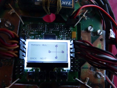
First flight with the PI set, these values are more appropriate for my quad:
Roll (aileron)
P Gain : 90
P limit: 50
I Gain: 30
I Limit: 15
Pitch (elevator)
P Gain : 90
P limit: 50
I Gain: 30
I Limit: 15
Yaw (rudder)
P Gain : 90
P limit: 50
I Gain: 60
I Limit: 20
Self Level settings
P Gain: 35
P Limit: 5
I Gain: 0
I limit: 0
What is PID control?
PID control in English means "Proportional, Integral, Derivative" control.
The p, means proportional gain, and is a value that is multiplied by the value of the error reporting system,
The i, means integral gain is the value that is multiplied by the total error reporting system, ie the absolute value or the total amount of error.
The d, means derivative gain, the value is multiplied by the derivative of the error value returned by the system and comes to show how fast is varying the error.
We could say that the proportional control (p) is acting as a spring, while the integrated (i) said damping spring effect, as in the case of a car buffer.
Following the example of the spring and damper, we can understand how it works.
Much proportional control (much gain p) the system goes into oscillation, the value must be placed before the oscillations, starting violent, little value makes uncontrollable the quad.
Much integral control (high gain i) harden the system goes to soft oscillations, little bit value do not damping proportional control, we must raise it until just before it enters soft oscillation.
The (p) limit = 100 or (i) limit = 20 is set a limit to the value calculated by the system, according to the motherboard manual is not necessary to touch them.
9-7-2013
Using a simple frame from HK (Talon Carbon Frame ) ,and the camera gimbal stabilized feature of the 1.5 firmware of the kk2, we achieved a stable horizon. The only problem is the vibrations of the stabilizers servos . Here are some videos:
Frame from HK (Talon Carbon Frame)
Using the HK Wing Camera II with plastic enclosure (shaky)
Using damper from a RC crawler to fix the vibrations, not bad
Using the Liquid Image Ego Quad ,Interesting action camera, very low weight (73 gr) Wifi and HD quality, another alternative to the GoPro camera.
Flight over Intempo Towers
Flight over Benidorm (La Cala).
The main problem is the vibrations of the stabilizers servos
This video shows how to balance the quad engines using the RD 32 Laser II and some tape.
When you put the tape, see if the vibrations increase, if they increase seen changing it around until the vibrations disappear.
I hope that with these tips you can get your quad fly reasonably stable and allows you to spend time a lot of fun and why not make those spectacular aerial videos always wanted to do, I encourage all a matter of patience, perseverance and not much money the result is certainly worth off.
NB Do not forget to consult and respect the latest legislation in force regarding the use of drones in your country
Legal:
All information transmitted in this article is for informational purposes only without warranty of any kind and for the sole purpose of helping others achieve achieve a particular purpose. Not guarantee any specific outcome or endorse any particular brand, all operations should be made respecting the personal safety measures that the laws of each country requires.
It is certainly a challenge to build a complete battery quadcopter below 130 euros, but it is also true that technology becomes more attractive when prices become popular in this price range I think it is time to leave us excuses to enter to undertake this mission (impossible?).
Certainly in this world where prices soar in some components have to tread carefully so as not to exceed that budget, to begin with I would exclude the emitter and receiver radio is never usually included in the kit sold in quadcopter the market, perhaps this can give us a little more room, however if you include the battery if it is a major element of the set but also in many kits not included.
All of us who, like me, who are new to the subject, approach this task, are struck by the technical jargon in use, which can sometimes make it difficult to make an appropriate and correct choice.
At the risk of simplifying the topic but to clarify it somewhat I would say that the critical essential elements (apart from the chassis) are the control unit that connects to the radio receiver and controls the esc or regulators stabilizing the device and translating our orders by accelerating or decelerating each of the 4 motors, the esc or regulators that in turn control the motors with energy and impulses, the motors and the propellers. The rest of the components, such as cables, connectors, batteries, etc., have more room to move.
If we use the + configuration and it is a quadcopter that we are going to mount, there is no problem because it is the one that comes by default and we will not have to touch any of the programming, which helps to simplify the matter a lot. If we go into the subject of esc or regulators and motors, it is where we see that the wide variety of motors and regulators on the market can confuse us completely. I think that more than indicating a specific engine we could talk about a range in the weight of the engine, its kv (turns per volt), its thrust and consumption in amps that will determine the esc or regulator to choose and finally the propeller
Going back to YouTube and looking for cheap configurations and what we see that work with the HK KK board we can summarize: